‘Relieving the Strain’ on your Wire and Cable Assemblies

Used to ‘anchor’ the wire or cable to a connector, the strain relief bends the component material in order to hold a product in place. A strain relief is also important to the electrical and mechanical integrity and overall performance of a cable assembly

For many years, the humble tie-wrap or cable tie has been the answer to cable to connector security, however over the past 15-20 years there has been a growing need for a stronger, more rigid alternative.

The main purpose for strain reliefs  in wire and cable assemblies is to withstand ‘bending’ and ‘pulling’ forces. This is accomplished mechanically along with the electrical connection needed to transfer the signal or power the connector must carry.  Once a strain relief is on the cable it is placed against a feature on the connector, a metal housing, a plastic housing or over mold that transfer the force from wire of cable to the body of the connector.  This makes sure the force is not exerted onto the connector’s contacts which are often not able to withstand any great force.

Not only this but adding a strain relief greatly improves the flex life and tensile strength performance as well as the overall design of your custom wire or cable assembly.

You might deem it unnecessary to analyse the features and discuss the pros and cons of a strain relief, but clearly the ‘little’ things do matter and can ultimately determine how successful our final product will be.


Low Smoke Zero Halogen Cabling: The Greener Choice

Low smoke zero halogen or low smoke free of halogen (LSZH or LSOH or LS0H or LSFH or OHLS) is a material classification typically used for cable jacketing in the wire and cable industry. LSZH cable jacketing is composed of thermoplastic or thermoset compounds that emit limited smoke and no halogen when exposed to high sources of heat.

Most network cables are insulated with polyethylene, PVC or some sort of thermoplastic. In a fire, a halogen-containing plastic material releases hydrogen chloride, a poisonous gas that forms hydrochloric acid when it comes in contact with water. Designated halogen-free cables, on the other hand, do not produce a dangerous gas/acid combination or toxic smoke when exposed to flame.

Low smoke zero halogen cable therefore  reduces the amount of toxic and corrosive gas emitted during combustion.

Low smoke zero halogen is becoming very popular and, in some cases, a requirement where the protection of people and equipment from toxic and corrosive gas is critical.

Other benefits of halogen free cable include:

  • It is often lighter, so overall cable network system weights can be reduced.
  • The environmental impact of halogen free cabling can be lower if there are fewer toxic chemicals
  • Halogen free cabling is also easier to dispose of compared to other forms of cabling that emit toxic gasses when burned and can be toxic to dispose of by other means.

Link

Make The Right Connections: A Definitive Guide to choosing the Right Connector

Make The Right Connections

Connectors are the base of any electronic product. They tie the entire system together. Connector failures are some of the most common component failures in electronic products. Unfortunately connector selection is often left to the end of the design of a product and is not given enough thought which results in quality and reliability issues for the product.

A Rationale on Heat-Shrink Ratios

1. Heat shrink tubing is a type of plastic tubing whose diameter shrinks when it is heated. The materials used to make heat shrink tubing vary, but include complex polymers and similar materials. Heat shrink tubing is most commonly used in electrical applications in order to protect, insulate, or repair wires, terminals, and other types of electrical connections. It extends the life of these items and ensures their good performance

2. Depending on the exact type of material used, there are two main ways that heat shrink tubing can work. Tubing can be specially treated during the manufacturing process to shrink when heated. This type of tubing is said to be expansion-based. When it is manufactured, it is heated to near its melting point and stretched to expand its diameter. It is then rapidly cooled in order to help it keep its shape. When heated later in consumer use, the tubing will shrink back down to the size it was before it was stretched in the first place.

3. Every kind of heat shrink tubing on the market has its own shrink ratio, meaning the degree to which it will shrink. Tubing with a two-to-one shrink ratio, for example, will shrink to half its original size. One that has a six-to-one shrink ration will shrink to one-sixth its original size. The needed shrink ratio will depend on the specific application the tubing is used for. Heat shrink tubing has numerous common uses, such as insulating outdoor wires and cables against the elements, grouping multiple wires together, and colour-coding wires for easy identification

4. Heat shrink tubing is the ideal way to create a tight, professional finish on any wire, hose or cable management project. Once shrunk, the tubing will hold its reduced state, even in elevated temperatures. Typical applications for the heat shrink tubing include: electrical insulation, termination, splicing, cable bundling, colour coding, strain relief, wire marking, identification, mechanical protection, corrosion protection, abrasion protection and moisture and weather sealing.

In Focus: The Terminal Block

shutterstock_86499385

Terminal blocks are types of electrical connectors. They provide a convenient means of connecting each electrical wire without a splice or physically connecting the ends. They are normally used in connecting wiring among different items of equipment in an enclosed space or to create connections amongst individually enclosed items.

terminal block is one method of connecting a selection of different electrical wires. Terminal blocks come in a variety of different shapes and sizes so you can normally find one that will be compatible with whatever project you are carrying out. The differences in terminal block can lead to problems if an incorrect type is used or if it is not connected properly.

Step 1 – Terminal Block Type

Look at the electrical equipment you are working on to see what type of connection it requires. Normally you will have either a screw-in or plug-in connection. Screw-in wires are placed inside the terminal block and screwed into position. This type of connection is common for equipment that does not require high voltage protection. A variation on the screw-in connection is one held in place by a spring mechanism. This connector can reduce the time spent on the job because you simply clip it into place instead of removing and replacing the screw. A plug-in connection has a male terminal at the end of the wire. This terminal is connected to the female port on the terminal block and forms a secure connection. Plug in blocks are commonly used in the fuse box of an automobile.

 Step 2 – Choose Terminal Block

Once you know the type of connection that is required, you need to find a terminal block that fits the rest of your requirements. Consider what space you have for the connection and how many wires need to be connected. Terminal blocks are supplied in a variety of shapes and sizes so you should be able to find one to fit your requirements. Next, choose the correct rating: 3, 5, 15 or 30 Amp terminal blocks are widely available. You need to buy the one that meets the highest current level that it will conduct in order to allow the most powerful piece of equipment to function.

Step 3 – Screw-in Connection

Always make sure that any electrical equipment is turned off before beginning work. For a screw-in connection, you will need to strip a small amount of the insulation from the end of the wire. Normally, around 1 inch is sufficient but this will depend on the component. Unscrew the retaining screw from the terminal block then insert the wire into the hole. Tighten the screw into place. Make sure that it is fully tightened because if the wire is left loose, it will begin to heat up and melt the insulation. Over time, this could result in a fire so take a little extra time to make sure that it is secure.

Step 4 – Plug-in Connection

Position the terminal block and run the electrical wires to it, connecting the male terminal to the female port. Press firmly to ensure that the connection is secure and won’t come loose in the event of any subsequent movement.

Step 5 – Test Equipment

Once you have made all the connections, test the equipment to make sure it works correctly. After testing, check the terminal block and the connections to make sure that there is not excessive heat build-up and the wires are still securely in place.


Protect Yourself: The Dangers Of Counterfeit Cable

shutterstock_158311769


If you’re worried about counterfeit cable, you have good reason to be. It’s one of the hottest topics in the cabling industry today as the prevalence of non-compliant cable continues to grow. It’s estimated that as much as 20% of the cable for sale now is unsafe, unapproved, or counterfeit.

So how do we identify the risks and hazards associated with purchasing counterfeit cable? From pricing to UL numbers, wire and cable material and jacketing as well as the weight of the cable and conductors inside the cable, all are key indicators to the reality of counterfeit material and goods.

The following link offers a fascinating insight into the dangers and risks of counterfeit cable!

Click to access Counterfeit-Cable.pdf

The ‘Blades of Glory’

wire blades


No I’m not here to talk about that moderately successful ice skating film starring Will Ferrell, this post is all about the wire processing blade and its properties.

As published in this month’s Assembly Mag, the humble blade does not get much attention these days, yet the importance of it remains vital to the success of your wires and cables.

Choose the wrong blade and your wire can become feathered – where strands of wire have been cut out completely,  if the blade cuts too deep it can leave marks in the conductors or it may not strip the wire at all.

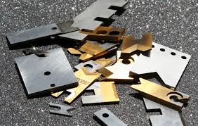
“For decades, manufacturers have relied on three types of blades to strip and cut wire: V, rotary and die. All blades are made of hardened tool steel, but each type is unique in design, function and capability”  1

So how do we know which blades to use for each wire and cable we use?

The first blade and for me the most common in cutting and stripping wires and cables is the V-Blades. Versatile and variable, these blades feature a 90-degree V configuration that provides good quality stripping and cutting of a wide range of wire sizes (26 to 10 AWG) and insulation types (PVC, Teflon, fiberglass)

V blades are used in sets (top and bottom) that bypass each other to cut wire. Stripping V blades penetrate the insulation at four points that, when connected, form a diamond 2. V-Blades should be the main choice of blade in most wire and cable processing applications.

Rotary blades, interestingly, are square, not round. Their name stems from the fact that the blades rotate around the insulation to strip it. With similar properties to the V-Blades, rotary tooling can cut up various sized wire and cable but at a much slower and less efficient pace. Interestingly, experts say these blades are not designed to cut wire. Instead they mark wire which is slightly thicker and rounder in shape.

Die blades are custom made to strip or cut a specific AWG wire. The most common die blade for stripping is the collinear radius (CL-R) type. It features a ground half circle at the center of its straight shear edge 3.

When a set of duplicate CL-R blades are closed around the wire, the circle’s radius matches the wire conductor exactly. This perfect fit produces precise stripping and clean shoulders without any conductor damage.

Die blades are often required for stripping tougher insulations, standard die blades strip 4 to 30 gauge wire, ground-edge blades strip 8 to 26 gauge wire and precision blades with guide strip 28 to 36 gauge wire.

So to conclude, the right blades are critical to your product’s success.

The most important consideration is the application range that it must process. Some applications only require a machine that can measure, cut to length, and strip one or both ends of a wire or cable. This is considered basic and can be done using a machine with a cutter head that can only accept one set of blades. In this case use the V-Blades.

With the rotary blades, “the rotary stripping head can be programmed to make incisions at any depth into the insulation, this design eliminates the need for changing blades (radius blades, die blades, etc.) when processing different wire or cable sizes. But the production rate is somewhat slower“4

The die blades should only be used when faced with cutting wire regularly that has tough insulation. It can cope with more material thickness that standard V-blades and rotary blades can’t.

HOPE THAT HELPS!!!


1 = http://www.assemblymag.com/articles/91830-cutting-it-close

2 = http://www.assemblymag.com/articles/91830-cutting-it-close 

3 = http://www.assemblymag.com/articles/91830-cutting-it-close  

4 = http://www.schleuniger-na.com/en-us/news-events/news/news/2012/03/01/choosing-the-right-cut-and-strip-machine-its-all-about-the-apps/